LOGAN
DATAPOINT CORPORATION
Joe;
Enclosed is a tape of LOGAN and NIM, along with some notes of explanation
for LOGAN. This program was written by Robert Bishop: a clever piece of
work. I have found it genuinely useful for working out logic sequences
before breadboarding or building them. Unfortunately, it does not accommodate
clocked logic. Maybe later.
NIM is one of my early efforts at writing game programs. It's amazing
how difficult it is to analyze strategy for simple games! (Note, for example,
the length of the program.) Taught me how to play NIM, though.
I thought we might trade programs, instead of me charging you $2 and you
charging me $2. The new monitor sounds good! The old one gives me problems
by inconveniently using up page zero locations. Maybe I can modify it.
Keep me notified of whatever other software you have.
This A/D described in interface works quite well, and has many applications.
Measuring shaft positions, voltages, light levels (with a CdS cell), tem-
perature, etc. are all good applications. I have a nice lunar lander using
a joystick which involves takeoff, orbit altitudes, etc. I will send it as
soon as I rewrite it (erased my only copy.)
Try this: In BASIC, type PRINT COLOR and see what you get. Or type
COLOR=100 and then PRINT COLOR. Seems to work as a variable with a mind of
its own. I don't know what it means.
Working on 16K chip problem. I can see now why the modification would
require a lot of jumpers. Every try to work with address multiplexing
Anyway, I'll document any successes and pass them along.
What kind of printer are you playing with? Where's that chess program?
Anybody try to interface a cassette operating system? Saw a photo of Jobs/
Wozniak in Mini/Micro, and industry mag.
Keep those cards and letters coming!
Harry J. Saddler
c/o Datapoint corp.
DATAPOINT CORPORATION
LOGAN: 9LOGic ANalysis) 4A.00FF/800.FFF
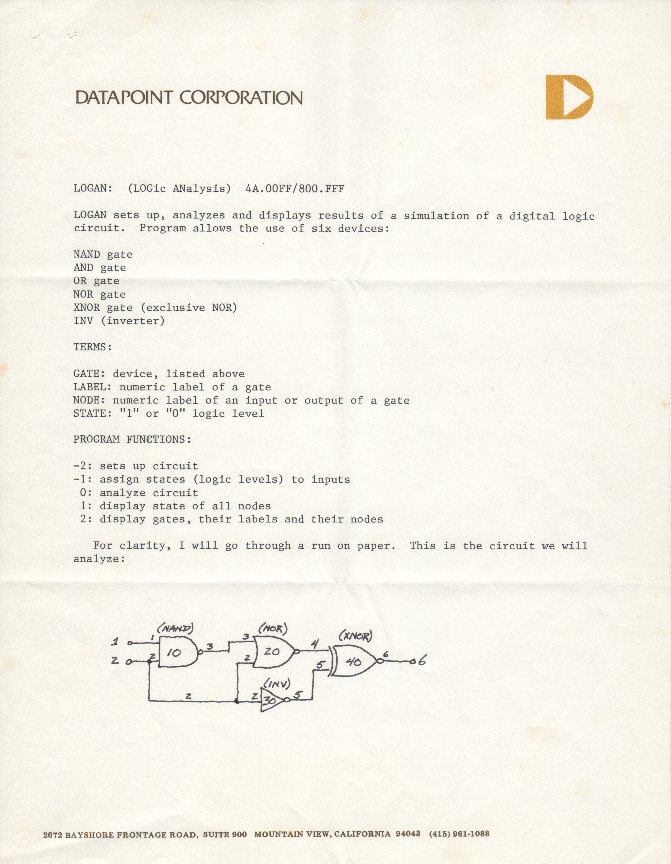
LOGAN sets up, analyzes and displays results of x simulation of x digital logic
circuit. Program allows teh use of six devices:
NAND gate
AND gate
OR gate
NOR gate
XNOR gate (exclusive NOR)
TNV (inverter)
TERMS:
GATE: device, listed above
LABEL: numeric label of a gate
NODE: numeric label of an input or output of a gate
STATE: "L" or "0" logic level
PROGRAM FUNCTIONS:
-2: sets up circuit
-1: assign states (logic levels) to inputs
0: analyze circuit
1: display state of all nodes
2: display gates, their labels and their nodes
For clarity, I will go through a run on paper. This is the circuit we will
analyze:
NOTE: * is a program prompt.
RUN......
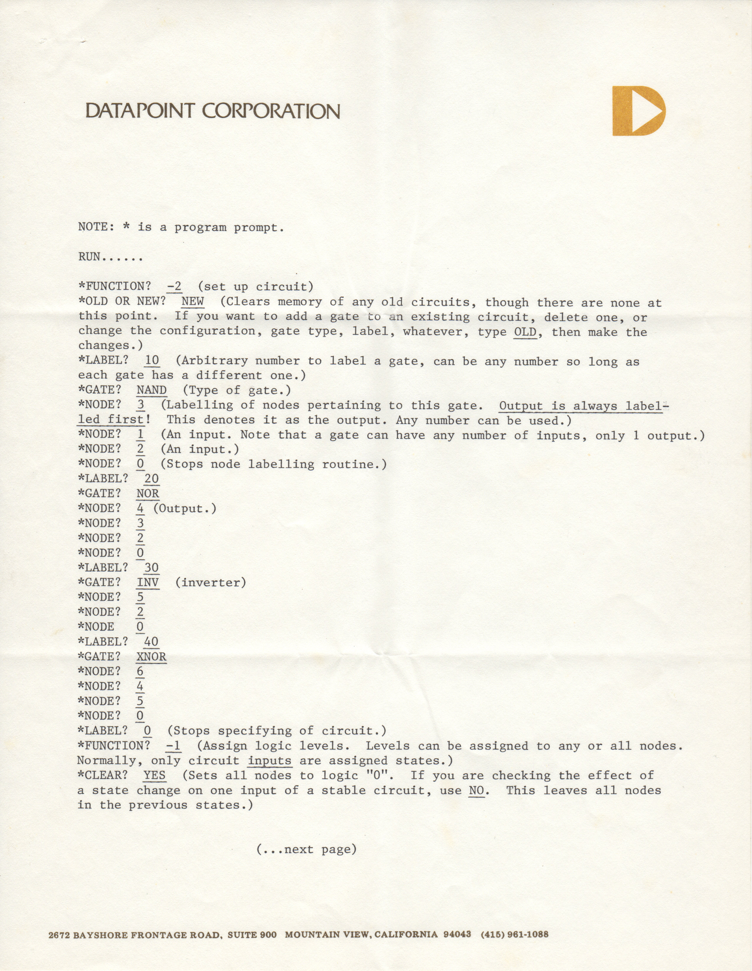
*FUNCTION? -2 (set up circuit)
*OLD OR NEW? NEW (Clears memory of any old circuits, though there are none at
this point. If you want to add a gate to an existing circuit, delete one, or
change the configuration, gate type, label, whatever, type OLD, then make the
changes.)
*LABEL? 10 (Arbitrary number to label a gate, can be any number so long as
each gate has a different one.)
*GATE? NAND (Type of gate.)
*NODE? 3 (Labelling of nodes pertaining to this gate. Output is always label-
led first! This denotes it as the output. Any number can be used.)
*NODE? 1 (An input. Note that a gate can have any number of inputs, only 1 output.)
*NODE? 2 (An input.)
*NODE? 0 (Stops node labelling routine.)
*LABEL? 20
*GATE? NOR
*NODE? 4 (Output.)
*NODE? 3
*NODE? 2
*NODE? 0
*LABEL? 30
*GATE? INV (inverter)
*NODE? 5
*NODE? 2
*NODE 0
*LABEL? 40
*GATE XNOR
*NODE? 6
*NODE? 4
*NODE? 5
*NODE? 0
*LABEL? 0 (Stops specifying of circuit.)
*FUNCTION? -1 (Assign logic levels. Levels can be assigned to any or all nodes.
Normally, only circuit inputs are assigned states.)
*CLEAR? YES (Sets all nodes to logic "0". If you are checking the effect of
a state change on one input of a stable circuit, use NO. This leaves all nodes
in the previous states.)
(...next page)
DATAPOINT CORPORATION
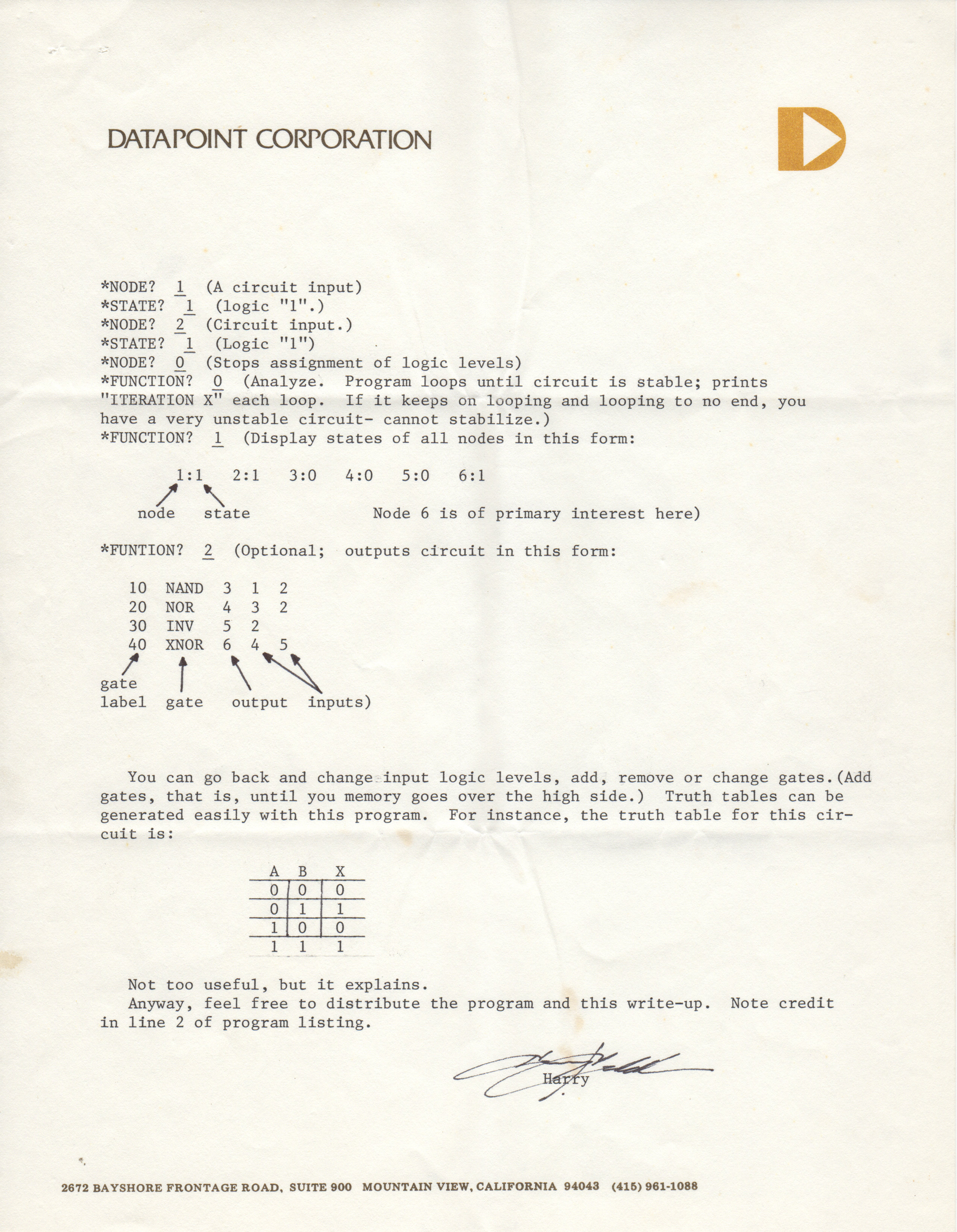
*NODE? 1 (A circuit input)
*STATE? 1 (logic "1".)
*NODE? 2 (Circuit Input.)
*STATE? 1 (Logic "1")
*NODE? 0 (Scope assignment of logic levels)
*FUNCTION? 0 (Analyze. Program loops until circuit is stable; prints
"ITERATION X" each loop. If it keeps on looping and looping to no end, you
have a very unstable circuit- cannot stabilize.)
*FUNCTION? 1 (Display states of all nodes in this form:
1:1 2:1 3:0 4:0 5:0 6:1
/ \
node state Node 6 is of primary interest here)
*FUNCTION? 2 (Optional; outputs circuit in this form:
10 NAND 3 1 2
20 NOR 4 3 2
30 INV 5 2
40 XNOR 6 4 5
/ | \ \__\
gate | \ \
label gate output inputs)
You can go back and change input logic levels, add, remove or change gates.(Add
gates, that is, until you memory goes over the high side.) Truth tables can be
generated easily with this program. For instance, the truth table for this cir-
cuit is:
A B X
0 | 0 | 0
0 | 1 | 1
1 | 0 | 0
1 1 1
Not too useful, but it explains.
Anyway, feel free to distribute the program and this write-up. Note credit
in line 2 of program listing.
Harry J. Saddler
c/o Datapoint Corp.
- Printer-friendly version
- Log in or register to post comments