
As I posted in a another thread, I just purchased an Apple II Plus for a great price. However, the power supply was DOA. There was no power coming from any of the pins. Since I don't know anything about Apple II power supplies but what I posted, I spent some time trying to diagnose the problem and couldn't find anything other than it had no output. I did read around a 320 volt voltage near the big honking transistor. But, otherwise, there was nothing.
So, I ordered the RIFA capacitor and all of the electrolitic capacitors. Today, I installed them and still had nothing.
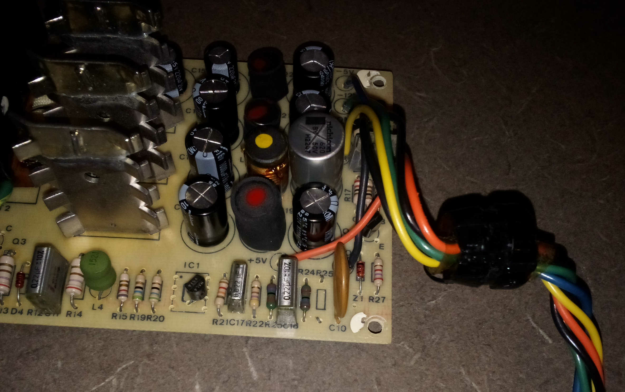
I decided to take a close look at the power supply board to see if any components were cracked or damaged and discovered that R25 had clipped off leads. The resistor was completely missing. I looked up the value and found it was 100k ohms. After installing the resistor I had power! I installed it in the computer and have life. :-)
What is really odd about this is the power supply was still rivetted shut. I have no idea why the resistor was missing and appeared to be cut out.
Were the original capacitors still there? They'd have been orange Nippon Chemi-Con caps, tall and thin.
And R25 is missing on both of my spare supplies - cut out like yours.
The original tall, thin, orange capacitors were installed. Some were very slighty bulged at the top. So, I removed and replaced them all because I was hoping to find a bad capacitor. When I checked the capacitors, none were shorted.
It's interesting that your R25 is missing as well. It sounds like they removed it at the factory for some reason.
That looks like someone recapped that, the orginals would be taller on the secondary. New caps are smaller like your current secondary. You may want to make sure they are the right caps and installed correctly. Someone without knowledge may ahve grabed a console5 kit and made a mistake...
Also the AA11040B (common in II+) was designed with an X class safety cap, and when working correctly should it fail it should fail closed which would, or at least should, blow fuse F1.
But since you've got voltage on the primary transistor your fuse is not blown. Just a good first check when a RIFA had failed. =)
Since you appear to be comfortable working safely with higher voltages, I'll assume you can read schematics. Are you aware the Astec schematics are avalable online? Searech for "Apple II power supply schematic 1982" on google an archive pdf link should be near the top of results. That should help troubleshoot the circuit. I'm a fan of this simple straight-forward design. The real question is if Q1 (?) is good
The Astec power supply manual says this on the AA11040-B schematic:
"* R32 and * R25: +5V output adjust resistor"
R25 is in parallel with R24, and R32 is in parallel with R23, so neither is required for the circuit to function. They simply strengthen the negative feedback. R24 is 2.7 kΩ, and R25 is 100 kΩ so not much is changed by using R25. That branch is 2.7 kΩ without it, and 2.6 kΩ with it in the circuit. It looks like the printed circuit leaves R32 out entirely.
Hello,
I re-capped it myself. All capacitor values are correct and the polarity is correct. I found it interesting that the polarity was marked only on the positive lead. I used the Astec manual, I found online, as it had a schematics and parts lists. The capacitors, including a new RIFA capacitor were ordered from mouser. I was hoping that by re-capping the power supply it would work again. (Some of the capacitors were slightly swelled.) While I didn't find any shorted capacitors, after I re-capped the power supply I noticed a high pitched noise when turning the power supply off. I didn't have that before.
After I installed the missing R25, that I found the value for in the Astec manual, it worked. :-) The computer has been running nicely for a few hours now. I did have some minor issues getting the keyboard working again, but it just required a bunch of key presses. Most likely, this computer hasn't ran in decades and had a little corrosion on the key switches. The 80 column board works , too! I'll have to install the shift key wire and, eventually, the 80 column soft switch. (It has a toggle switch now.) The floppy drives, that are possibily non-functional, were shipped today. (Why buy something that works?)
I'll have to get the power light ordered as well, as it doesn't work. That's minor. Another minor issue is the reset key is missing the key cap. I'll keep an eye out on ebay for one.
jeff d wrote:
That looks like someone recapped that, the orginals would be taller on the secondary. New caps are smaller like your current secondary. You may want to make sure they are the right caps and installed correctly. Someone without knowledge may ahve grabed a console5 kit and made a mistake...
Also the AA11040B (common in II+) was designed with an X class safety cap, and when working correctly should it fail it should fail closed which would, or at least should, blow fuse F1.
But since you've got voltage on the primary transistor your fuse is not blown. Just a good first check when a RIFA had failed. =)
Since you appear to be comfortable working safely with higher voltages, I'll assume you can read schematics. Are you aware the Astec schematics are avalable online? Searech for "Apple II power supply schematic 1982" on google an archive pdf link should be near the top of results. That should help troubleshoot the circuit. I'm a fan of this simple straight-forward design. The real question is if Q1 (?) is good
Turned the Apple II on, today, and it doesn't boot anymore. There's a clicking coming from the power supply. If I disconnect the power supply, I can read the proper voltages on a meter. So, I removed all the cards and same problem. I am wondering if the power supply isn't supplying the proper current and shutting down or if there is something shorted out on the system board.
In post #3, "reifsnyderb" wrote:
" When I checked the capacitors, none were shorted. "
Uncle Bernie comments:
Just to prevent misleading anyone reading the post #3, electrolytic capacitors typically don't fail towards a "short circuit". Those who do produce a short, explode first, and the explosion causes shredding their guts (aluminum foil and paper) and then they may produce a short, too, but this mess is so obvious that any misconception is avoided.
How electrolytic capacitors usually fail is caused by evaporation of their electrolyte, since they are not hermetically sealed. The black material you can see on one end actually is a rubber plug which seals everything in the aluminum can like a cork seals the wine in a wine bottle. But over time (decades if at low temperature and if lucky, but only a few years if running hot), the electrolyte is gradually lost and the effect is some loss of capacitance and increased ESR.
The former is not very useful to discern dying capacitors by measurements because you don't know the initial capacitance the particular specimen once had when new and at which temperature it was. Measuring the ESR is a better method. Few hobbyists have the instrumentation to do that. But a higher ESR also means more ripple voltage and this can be seen with an oscilloscope. You need to know the ripple voltage specs of the particular power supply to see if it's dying. When it's already dead, you can see nothing.
Replacing electrolytic capacitors of switchmode power supplies is tricky as you need special types rated for the maximum ripple current at the switching frequency (and its relevant harmonics) of the power supply. This boils down to a low ESR at higher frequencies. Which keeps the losses within the capacitor low enough. Common, cheap electrolytics meant as filter capacitors in AC power supplies won't cut it. If used in a switchmode power supply, these usually overheat and may explode when the electrolyte turns into steam and builds pressure. This is why modern electrolytic capacitors have pressure relief kerfs which just "pop" open, and prevent a worse disaster.
In the realm of professional electronics, switchmode power supplies are considered to be non-repairable, disposable items, and for valid reasons. If they fail, they are replaced with a new one and the bad one is disposed of.
This is why I have chosen to replace my failed Apple IIe power supply with a new "Mean Well PT-65B" and described the mod here on Applefritter. Despite my professional background which included the design of switchmode power supply controller ICs. The PT-65B, also available from Mouser, Digikey, and other distributors is probably cheaper than a set of the correct, low-ESR, switchmode power supply rated replacement electrolytics.
The bottom line is, don't try to repair these old inefficient power supplies, it's not worth the effort and risk, just rip the old PCB out, and put a PT-65B in.
- Uncle Bernie
I ordered a PT-65B yesterday and already have the 7905. I still had to try to repair the thing. :-)
I agree with you on the increased ESR (and everything else you've described) but my experience has been that well before the capacitor starts to lose capacitance, it gains significant capacitance (although this is not reliable). I've measured dried up electrolytics with 3 -5 times their nameplate capacitance. Of course, this is in a tester at low voltages. The story is a bit different at higher voltages.
In the Apple II (Astec) power supply I have only ever seen one failed capacitor. The little stubby 220 uF one near a power resistor that always runs hot by virtue of being beside that resistor.
When it fails the power supply doesn't start up at all. A general purpose power supply cap works fine there, but I always replace it with a 105°C model of 25 volts instead of the 16V it was iniially rated for.
More weirdness. Ok, I decided to keep trying and removed that 100k ohm resistor (R25). Now the power supply works again. It's odd because when I turn the power supply on it clicks for a little while then finally boots. If I shut it down and start it back up, it boots up right away. I checked the voltage across one of the 74 chips and it's 4.90 volts....which is probably ok.
I noticed that if I install the 80 column card, it takes longer to boot. It's like it has to charge up, depending upon the load.
Maybe I wasn't letting the power supply sit and click long enough? lol It still doesn't seem right.
Edit to add: I just went back and tried to boot it up with the 80 column card in and it didn't boot. Once I pulled the card, it booted. Once it boots, then I can turn it off, install the 80 column card, and it will sit, click for a while, then boot.
I think the best course of action at this point is to trash the power supply. There may be something weird going on in the feedback loop of the switching power supply.
As Uncle Bernie suggested, when there is an over arching system failure in the supply that is not easily diagnosed, then just get a replacement.
If you want to keep it looking "stock", then a Universal PSU replacement kit from ReActive Micro is what you want. That way no one will ever know that you have a brand new power supply good for another 25 - 30 years.
Look here: https://www.reactivemicro.com/product/universal-psu-kit/
Yeah, I know. I've got a Mean Well power supply on order. But I'd still like to see the original work. It almost works fine. It just doesn't quite work right.
Ok. Ummm.....yeah, I think I found the problem. I just happened to notice that the 680uF capacitor felt loose. It really wobbled around. So, I pulled out the power supply board and checked the capacitor. The leads didn't have a drop of solder on them. It turns out the idiot (me) who installed the capacitors didn't solder this one capacitor. I don't know how that idiot missed it. But, yeah, the computer boots up a lot better now. Thanks to everyone for all the help, advice, information, etc. Here it turns out the problem was between the chair and keyboard all along.
While UncleBernie brings up the electrolyte I figure ti's a good opportunity to highjack this thread for a moment to address something that is a related issue with the RIFA caps, because I think it's a good example that demostrates AGE really is a factor with old caps. The RIFA on the AA11040B is an X-Class safety cap which means it's connected between line and neutral (I've heard it called common too) was designed that when it fails it should fail closed, which would be a short that in the AA11040B design (and others) would cause F1 to blow. That's a common design and found in the AA11040B, so even tho the RIFA was designe to never fail or flame out (the latter seems to still work well) the failure should blow the upstream fuse. But... we've found lots of supply still works with a dead RIFA! It seems only a rare few cases does F1 blow too. One could wonder, how is that possible with this design?
The answer could lie in the same cause, dried out caps. This could be either just an age thing, these caps are rated with a shelf life of 10 years, and every manufacturer will tell you these 30+ years old caps should be replaced because they can't gurantee they matrerials will survie that time even in the most gentle environmental conditioins. Heating/Cooling cycles stress the encasing plastic/epoxy and either normal use or hot storage units over years can cause cracks in the old plastic which would allow the elecrolyte to dry out and at that point all bets are off. We've seen RIFA caps with cracks or completley blown apart, and the supplies still function. Some users leave the failed RIFA in place and never replace. I don't think that's a great solution because the filter effect is a two-direction street and this not only protects the II from AC line noise, but also protects all other powered devices from any noise generated by the II. Luckily, almost all other device in the world today have some input singal filtering so the II back feeding noise shouldn't be a problem. But colder equipment or simple devices without built-in filters can be affected.
Are you talking about C7 on the AA11040B? If so, I think the heat is caused by the voltage spikes and ripple. The ripple on that cap can be high and voltage can spike above the 10V rating, so yeah either 16 or 25V but would also look for a high ripple and long life cap that are available from the big suppliers designe for SMPS like Nichicon UPV, UCA or Chemicon LXY series or their related cousins.
I've seen many AA11040B supplies and have seen a few of the secondary output caps burnt out. I'm not sure of the history, but looks like shorts because there's carbon near the pads. But in general, I agree the original caps often hold up very well, but for how much longer?
Which RIFA are you talking about and can you please provide a link to the schematics of this PSU?
I see you got the problem found of a missing solder joint, so that's good. Embarassing as can be, but happens to everyone at least once. =) Or maybe not, but easily could!
One comment on the replacements, I see you ordered your own replacements RIFA from mouser so I expect you likley did the same with the otheres. One thing that can get missed is the original caps were -10/100 which are hard to find today. Most are +/-20% so it's helpful to check the replacements before installing to make sure there are not ones with capacitance lower than -10% because that may cause issues with output power.
If this is a II+ you very likely don't have conventional "switches" at least not the kind you're likely thinking of. May of the II+ models have a very funky metal sheet which is sandwiched between the key actuators and a PCB with contact points. You may want to look around for examples, I know I've shared examples of what I found which is even the tiniest bit of corrosion (microscopic dots) is enough to cause the swith to fail. Don't use any of the "standard" cleaning methods because you'll only make things worse for yourself. You'll also need to be careful because if there's any changes to the key "leafs" you can run into problems with contact and keys which work worse after fixering. To fix the problem I found was to scrap off the corrrosion and that took a lot of careful work under a scope. There may be better ways (maybe a pink perl eraser?). I was super carful because the landing pad is critical and any damage there would be bad. The other thing to note is the lading pads are gold plated so those shouldn't corrode, but the swith leaf and contacts are aluminum so this seems to be a case of electric current flowing through dissimilar metals (galvanic bonding?) so even a little white oxidiation on the leaf contacts should be removed too otherwise the problem could resurface shortly. I know gold/tin issues, but I don't know gold/aluminum only suspect something similar is happening here.
Glad you got that figured out!! I love the original Astec design, simple and effective. Maybe a little low on power, but today that should be a moot point unless you've got a ton of old cards installed otherwise it should do you well.
I suspect C7 may have been the biggest problem on my power supply. While I don't have a good way to test it, I've noticed that if I put an ohm meter on a good capacitor, it's resistance climbs. C7 is the only capacitor that does not act in this manor as the meter shows it is completely open.
While OT, my 80 column card failed and the video was blurry and multi-colored at times. I also noticed a lot of corrosion on the pins of many chips. Some of these chips appear to have copper pins, too. So, I spent at least an hour cleaning the pins of many chips carefully with a pencil eraser. The video is fixed and the 80 column card came back to life. :-) Two more items are on the list to repair. I need to get a key cap for the reset key and fix the power light. (The bulb appears good and no power is getting to the socket.)
I forgot about R25, I checked 5 of many boards I have which are currently awaiting their new caps to be installed (should happen any day) and found all have R25 populteded. But... they also all had different values. I didn't bother to read the values, only noticed different values. I'll get the values when I get the caps installed.
The AA11040B which I think you have the schematic for, and there's only on RIFA on this board I think it's C1 (going off memory). Still going off memoory, but thought the design has C1 just past the fuse and mabye some inductors so if C1 fails short F1 would blow. Do I not remember that correctly?
I think the Dynacomp version of the IIe supply which was a cost reduced version of Astech's AA11040B replaced two MOVs found on the Astec design with Rifa but I'm not sure and will just leave that here for now until I have time to check later.
Yes, the PSU schematics in the Sams Computerfacts Apple IIe book do show a 2.75A fuse before the RIFA, but my guess is that when it shorts the RIFA doesn’t need that much current or time at 120V to blow up. I mean 2.75A at 120V is 330W.
C7, yes. Which is right beside R4, which gets pretty hot. That, and it's 10V and 85°C rating.
LOL, yeah those are curious specs. I think Apple released a service bulletin that suggested 16V replacements, but 25V may be better just gotta find one which keeps the balance. That neighboring ceramic resistor is HUGE, definately not 1/4W heck may even be more than 1W! I never really thought about if 85C was silly in that role, but have seen heat marks on the DynaComp boards which have a similar design that makes sense. Anyone ever grab a thermal image? Personally I am more comfortable with 105C compoents on primary, 85C is fine for the secondary provided some that heat can be pulled away with the enclosure.
Yeah I think it's a fast blow 2A fuse at that, so definately would be pretty quick!
Do you not have the Astech document from '82 with the schematics and BOMs for several of their supplies to the early //e days?
If not, I think it's better than the SAMS book but I do like the SAMS singal pictures. As I've been troubleshooting supplies I've been capturing some of the same images with modern gear. Much better resolution than found printed on the orignal newsprint pages. =)
The Astec docuement is very nice, lots of great information. You may not need it, but the final few pages they provide a pretty decdnt education on what the SMPS is and describe the circuit design and how it works. There's some great design stuff in there.
If you are saying that the PSU was still working after the RIFA has blown up, then the fuse was obviously not fast enough. This is the only way that can happen on PSUs with a fuse before the RIFA, like the one in the SAMS Apple IIe book.
Are you saying that because of my prior comment on the RIFA failing short, or something else?
There are many cases in the modern day where the RIFA fail and are destroyed but the supply continues to operate (ie fuse isn't blown) which I suspect is a result of the age of the cap and an internal breakdown.
aa11040B input.PNG
Yes, in post #15 you were asking why most of the time you observed that the fuse doesn't blow when the RIFA does, and I am answering that it is because the fuse is not fast enough. It's the only possible explanation.
Why are you taking time into account? C1 should fail dead-short under all circumstances and we aren't seeing this behavior.
I don't agree there is only one possible explanation, there are others including the RIFA isn't behaving as intended.
For example, the RIFA cap was designed to run for a few thousand hours and never intended to work after 30+ years. Do we as users care? Apparently not! As a result of its age, it's no longer capable of doing its job effectively. This failure mode should short line to neutral and even if F1 fuse fails to blow (it shouldn't) the breaker would soon trip. But if the old plastic case or potting compound cracks as a result of age or excessive heating/cooling cycles it's possible for air to enter the cap at which point all expectations are irrelevant.
We're seeing systems with destroyed C1 caps, and these caps were designed to self-heal, not explode, not catch fire, and fail gracefully but this isn't happening. C1(s) are exploding and neither F1 blows nor the breakers trip. Instead these systems run as if nothing is wrong, just without AC filtering. AFAIK, this is not how the supply was designed to operate. There's lots of hate for the RIFA online, but it's a hell of a cap, very robust and does a good job under the conditions it was designed to meet. If I had the gear to produce the failure conditions I'd be happy to test this out. but I don't. If we were to test F1 blow times I expect we'd see fairly fast response. I saw one fail once, the time between starting to glow and burning out was faster than I could flip the switch and finger was on the switch!
What is then another explanation of the fuse staying intact, after the RIFA blows up?? I am taking time into consideration, because it takes time for the fuse to heat, melt and interrupt the circuit. When the RIFA shorts the mains line to neutral, it blows up faster than the time required for the fuse to melt.
You can also look at it from energy perspective and say that the fuse stays intact, because the energy required to blow the RIFA when it shorts is smaller than the energy required to melt the fuse. But time is still a factor, since energy is defined as power multiplied by time.
Yes that all makes sense I totally understnad what you're saying and agree if that were to happen then the fuse wouldn't blow. But you're ignoring the RIFA shoud NOT fail in the way you describe. The requiriements of the safety ratiings guarantee the fuse would have enough time to blow when the cap is "good". To assume the original RIFA will work today is outrageous. Some may, but given thier application and construction it's really insane. No one should expect the original RIFA to work correctly after 30 years even if it just sat on a shelf, and these have seen use over the year. These capacitors were designed to withstand very specific conditions in a defined way and tested to verify they meet these requirements. Life expectancy was less than 15 years. People should undestnad and accept this.
CVT wrote:
Totally understand what you've been saying about the power, but you may want to check the power requirements of the ratings, which has a higher power rating the fuse or capacitor?
These fuses are very durable with high requirements because safety is primary focus. But after 30+ years of use or storage... they stop working as they should.
Failing in a way that doesn't blow F1 in this design would mean the capacitor did not work as it should have.
Imagine the result should a Y-cap fail the wrong way?!?!? It's not good, but at least modern US NEC requires additional protections which can help avoid that risk when line gets shorted to ground.
RIFA capacitors don't have power ratings, so there is nothing to compare. They only have a maximum voltage rating. You will not find a datasheet that says: this RIFA capacitor will crack, fill with moisture, short and explode one day, and when it does it will draw this much current for this many milliseconds, so choose your fuse accordingly. :)
Here you are simply stating the obvious. Nothing in the PSU should explode, so the RIFA definitely did not work as it should have.
I still don't see an alternative explanation to the one I provided to your original question (which was why the fuse stays intact after the RIFA blows up) in anything that you have written so far.
I would suggest that the RIFA capacitor fails in an open state, (it's an "open" device by definition at low frequencies) and very likely can't handle the current the fuse is asked to carry at the time of its cascading failure.
Well, it first fails in a short state, in order to explode. If it simply fails open it would never explode. After it explodes, you can say that it permanently remains open, since most of it is gone. I have done shorts between the 220V mains line and neutral as kid and it's a pretty violent event. There is a huge spark and a loud bang, traces get instantly vaporized and screwdriver tips melted.
The point I was making is that it takes less current to destroy the RIFA capacitor than the fuse's ampacity.
The failure of the capacitor is not a full-on short - it's a cascading failure and heating of the dielectric and conductive components of the capacitor, building up internal pressure as it happens until it ruptures. Normally the occurance of RIFA capacitor failure is not sudden or immediate due to a dead short. It happens over time, in the order of tens of seconds or minutes (and often happens over the course of weeks as the dielectric breaks down and can no longer self-heal) until terminal failure. A 2.75 amp fuse may not care that this is happening.
There are lots of videos on YouTube of RIFAs blowing up in real time. Sometimes they take a few seconds, other times it's a pop lasting under a second. I think the latter ones are pretty much a dead short, while the former might be more of the cascading type where they turn into a low resistor. The one that had blown in my Apple IIe PSU must have been a dead short, because there was very little of the capacitor left and the inside of the PSU looked like someone had sprayed Pepsi everywhere.
I've bought a few //e units over the years that had blown RIFA caps in them. Some of them blew the fuse, some didn't. The only RIFA I've had blow on me while I was running the machine was in a Franklin. I had just bought the machine and was planning on pre-emptively replacing the RIFAs like I normally do but I was testing the machine. Not soon enough... the cap popped with a smelly puff of smoke after less than 5 minutes of the machine being on. Lucky it didn't take anything else with it. I just replaced the RIFA and it worked. I have another Franklin power supplty here that wasn't so lucky, even after replacing the fuse and the blown RIFAs it doesn't work. I'm planning on replacing the board with a Mean Well PT-65B. I did the same thing with an Applied Engineering power supply and I am quite happy with how it turned out. I posted about it on another thread a while back.
How will that work? PT-65B power supplies only have three outputs - +5V, +12V and -12V. You need -5V as well for an Apple II to work.
You have to get a -5vdc (7905) voltage regulator and connect it to the -12vdc. It probably wouldn't hurt to put a capacitor on the output as well.
You just derive -5V from the -12V with a cheap 7905. It's not like you need a lot of current on the -5V rail.
Lots of us have done it.
Rebuilding Apple II Power Supplies – I Like 8 Bits
Chesh
The RIFA is a safety cap, which means is has ratings, UL 1414 is a good place to start, but there are many others because these requirements are different all over the world. The manufacturers can't put any of those symbols on the caps if they can't meet the requirements. For the US, the UL requirements has a power it must be able to withstand to get the rating.
I don't disagree with you that, the RIFA destruction would be the reason why F1 would remain fine, but.... that should NEVER happen. My questions have all been with respect to C1 failiing as is should and we all know it isn't doing this.
You seem to be missing this point, a X-class RIFA should NOT self destruct never ever ever. That's what I've been trying to point out, but I'm obviously not doing a good job of expresing that. As an X2 safety cap should (if it wasn't 30 years old) be able to easily handle <400V in a dead-short mode for enough time to allow F1 to blow. But we are seeing this doesn't happen, and that shouldn't be overlooked by anyone. The RIFA should not do this under any circumstances. Because they are failing in a way where F1 doesn't blow proves we should not be using a 30 year old X or Y safety cap in these computers and expect them to behave as designed. Again, X-class is a speacial condition because if it fails correctly F1 blows and system is offline, if it falis open we just loose the filter. But the design was for F1 to blow so the owner is required to fix the problem of C1 failing. The Safety cap does more than just fliter noise, it's also responsible for handling large current and voltage spikes which could otherwise destroy more sensitve compoents downstream.
And if we were finding Y-class cap failing in any other mode other than open.... that could be a deadly problem.
Safety caps should not be trusted after their expected life has passed. They may "work" but they aren't really doing all the jobs they were meant to do.
Search for the thread started by Uncle Bernie I think. I posted pics of how I added a 7905 regulator to get -5V and how i fit it in the AE power supply case based on his example with an Apple PS. The Franklin one will be similar but the form factor is different.
Not sure where are you are getting this from. Where did I ever argue that that any component in the PSU SHOULD self-destruct??
Of course you didn't, but that's also not my point. Let me try it this way... this is my point:
X-class safety caps are designed for a specific behavior, they are tested to verify they meet specific requirements, and respond to adverse conditions in a specific safe way.
The 30 year old RIFA's are not capable of doing this anymore, if they could every single RIFA failure would be accompanied with a blown F1 or tripped breaker.
An X-Class capacitor (from RIFA (Kemet) or any manufacturer) should not self destruct, it should actually self-restore, and when fail it should not self-destruct. The requirements are available for review.
These 30 year old caps are no longer able to do their job. It makes no sense to argue there's any acceptable reason for what we're seeing with these caps. It can be described in mayn ways, but bottom line is the capacitors should behave how we're seeing.
What's also being missed is, this is happening under normal AC line volatges (120 or 240VAC). Sure Youtubers, are going above but this is all not relevent to this discussion, they're basicallly duplicating rel-lab testings stuff and everything has a fatal failure point.
If the response we're seeing (even cracked let alone blown apart) was to happen under 1.5kV pulses after 30 years that shouldn't be surprise but that voltage is not common! But for an X2 cap to meet its requirements it would need to be able to withstand 2.5kV pulses and if fails, fail in safe way. If not, it does not meet the rating requirement and would not have an X2 rating. The 30 year old RIFA is no longer able to meet the ratings requirements so it's no longer an X2 rated capacitor.
If that is your point, I don't think anyone would disagree with it. But perhaps you should have started with that, instead of asking why the fuse stays intact when RIFA caps fail, or suggesting that RIFA caps have a power rating, which they don't.
The question asked in post #15 was really more retorical and followed with one very probable answer in the next paragraph which is age matters. Yes your reason of why is totally plausable, except C1 should not fail before F1 blows. This only can happen when C1 is bad and destroys itself. Household voltages are not enough to destroy an X2 capacitor even in dead-short conditions. This is where factors such as: age, enviromental coditions, materials durability are important.
This is an x-class cap, the rating requres the capacitor to handle minimum power levels before failing. It's not published or printed on the cap because X2 has a defined set of rating requirements which comes with an X2 rating. (e.g. operating voltage: <400V) A 250, 275, 300V X2 still needs to meet the same power threshold before failure to get the X2 rating. Everything is defined in the ratings documentation.
It sounds like we agree, old cap can be bad news.
The average jane/joe should understand a 30 year old caps (except ceramic) should not be assumed nor expected to work correctly. They may, but there are clear risks.
I think it's important for those of us that understand this, help educate those that don't and maybe this discussion helps with that.
Here is an illustration of why you can't expect normal behavior from 30+ year old RIFA caps...
rifa1.jpeg
rifa2.jpeg
That was one I removed from a //e that I bought off eBay a while back. Thankfully the machine was "untested" because if they'd plugged it in and turned it on that would have smoked for sure, probably instantly. It's pretty common to find these this bad or nearly so. That hard translucent plastic gets brittle and cracks with age and then... POOF! It probably blows way faster than it is supposed to, which is why it can go and not take the fuse sometimes. A good new cap shouldn't do that unless it is faulty, but that happens sometimes too.
Are you kidding?? Mains 230V AC will blow a dead-short cap to smithereens! That was the condition of the RIFA in my Apple IIe PSU.
I think even US 110V AC will blow up a lot of caps if they are shorted. I've seen some caps from various electronics that looked like they popped pretty good. And a lot of them weren't nearly as old as an Apple II. I had a 10+ year old Samsung 32" LCD 720P TV that went bad a while back. It was a blown cap in the power supply for the back lighting flourescent tubes.
Sure it will if the capacitor's dielectric is rated for 25V or 50V...
But an X2 Rated capacitor is designed to be able to withstand 2.5KV transients and since it's placed across the line, it sees 120V (or 240 V) constantly across its terminals.
In the old days we used to put 1KV 0.01 uF ceramic disc capacitors across the line on the incoming voltage and they held up for decades.
We are talking about a cap that has developed an internal dead-short here, not a working one.
Pages