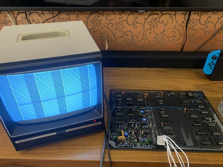
I have been replicating the SWTPC GT-6144 graphic terminal since I saw from Apple1Registry.com that it was one of the peripherals used with Apple 1 and it gives graphical display capability to the computer. It displays graphic by the 6144 dots (64 columns x 96 rows matrix). I am hoping to display the famous startrek Enterprise demo picture from Apple 1 replicas and create some new graphics for Apple 1s. So far, I could only obtain a display as shown in the picture when I applied power to the test board from a meanwell PT65B PSU.
Since it was not connected to any signal source, it SHOULD display what are kept in the 1K static memory ICs in a dot pattern. Apparently, I am still not there yet, it just stays in the same pattern in multiple switch on and off.
Anyone is familiar with transistors? The only thing I didn't follow the schematics is the transistors. It uses TIS58, 2N5129 and 2N5139, which seems to be too old and rare to find. I use 2N3819, 2N3904 and 2N3906 instead based on info from some online forums. Does anyone know the closest but easy-to-find alternatives of TIS58, 2N5129 and 2N5139? I also did the jumper per 60Hz configuration I remember.
I read somewhere there someone has tried to hook up a GT6144 with an Apple 1 replica but does any one know if the gentleman already succeeded in doing so? Would be great if we know how it is done.
Hi Mike,
your project is amazing and I really hope you will make it work.
I had a quick look at the transistors you mentioned and I find out some equivalent:
TIS58 (FET N-Channel): 2N5457, BF256A, 2N5485, 2SK107
2N5129 (NPN): 2N3641
2N5139 (PNP): 2N4121, BC231
I'm going to ask to someone more skilled than me to refine the search and I'll be back ASAP.
Good luck, in the meantime.
Regards,
Claudio - P-LAB
This is an awesome project!
You transistor substitutions should be fine. The PNP Q3 and NPN Q4 bipolar transistors are acting as simple switches with bases connected to logic levels, so the general purpose 2N3906 and 2N3094 should work just fine, regardless of the beta. Likewise for the JFETS Q1 and Q2. This is a fairly low frequency circuit (15 kHz) and the driver currents seem adequate. Q1 is a sample and hold switch, either all on or all off, driven by the -12V supply (pulsed off by Q3 for the hold). Q2 is a phase detector, also either all on or all off, so any replacement will do.
The output looks OK. The ON/OFF bar pattern could just be the RAM chips you have installed. See if you can change the pattern by switching the RAM chips around. Have you tried writing some points to the input port?
The horizontal lines could be a truncated horizontal blank at the end of a block. Are there 96 of them?
You could start by checking for the 15.84 kHz signal at IC23 pins 5 and 6. From your output, I expect it's good. You should check the horizontal sync pulse at pin 8 of IC17. It should be about 4 usec, also probably good. And the vertical sync pulse at pin 6 of IC11.
Then, check to see if the memory address counters are working (probably at least partly working, since you are seeing vertical bars). After that, it's a matter of tracing through the data latching and counter/command multiplexing and RAM write/read.
This will be an interesting project to follow.
Dave
Thanks Claudio and Dave for your inputs!
I haven't replaced Q1-Q4 yet (Q1-Q2 2n3819, Q3 2N3906, Q4 2N3904). Without connecting to any other board and just applying power to the board, IC23 Pins 5 / 6 and IC17 pin 8 give 50Hz sine signal rather than the 15.84KHz signal and sync pulse which Dave mentioned. Adjusting the 3 pots don't change any thing as the assembly manual described. +5V and -12V rails look good though.
I see J1-Pin 5 should lead to a 6Vac Ref, which is not connected to anything, what should I connect to this pin?
Screenshot 2024-01-03 170045.jpg
The power supply that would have been optionally purchased alongside the GT-6144 was Southwest Technical's P-197 (same one was used for their CT-1024 terminal which shares some design with this board). The 6VAC is there to act as a frequency reference to either stabilize the video (or to make it work in the first place, I'm not sure). Here's the P-197 PSU's circuit info. This small current AC rail is just taken from one of the transformer's secondary windings that happened to be at 6V, see schematic.
It's been awhile so maybe you've got this going already. This board was a oddball product. It was not very useful, as far I'm aware little to no software was ever created for it (on any platform) that was distributed beyond the user themselves hacking around with it. The nice thing is that it's got a command-driven parallel data interface so you can rig one up to pretty much any of these early computers and make it do tricks, if you want to. But of course it also requires a second video display too! No wonder success would have been a heavy lift for it.
Oh and again, it's been a while so maybe you've got this figured out. But FYI static RAM of this era anyway often has "default bias" data, and can come out of power up with the same random pattern each time. This has confused me before debugging other ancient video hardware. May or may not be the case with what you're seeing, but just an FYI that if it's random, but the same random on every power up, it could quite easily be working as designed.
Thanks for your input. I just came across SWTPC P197 and understand it was used in both CT1024 and GT6144. I haven't studied the schematics of CT1024 but I read from some other sources that the 6.3Vac is fed to a resistor-capacitor ladder and perhaps it is used to create a "clock" for the board? Anyway, I just replicated the SWTPC P197 and made some minor changes to the GT6144 gerber, and just sent the gerbers to the board shop for sample boards and ordered a custom-made 30W transformer (110V to two 6.3-0-6.3, I have to make guess, since the schematics just mentioned the model number "36 P 48" but I couldn't find any datasheet from the web). Will post an update after I receive the boards.
In post #5, bzotto wrote:
The 6VAC is there to act as a frequency reference to either stabilize the video (or to make it work in the first place, I'm not sure).
Uncle Bernie comments:
Your conjecture is close, but still a miss.
This trick was used in some video generator hardware to avoid "beat frequency" effects visible on the screen. While the human eye can't see 60 Hz events, it can see faults in the picture that may be caused if the field frequency of the video generator is off from the line frequency by a little bit. The most prevalent of these effects are:
a) unstable picture, picture slowly wobbling or wandering around
b) dark "hum bars" in the picture
These effects went away long ago due to three factors:
1. Vacuum tube TVs disappeared and transistorized ones can have much better stabilized internal supply voltages, with only very little residue of the rectified line voltage left (typically 120 Hz for 60 Hz line voltage).
2. Black level sampling / restore circuits in the TVs were improved, too: each TV "captures" the black level somewhere around the horizontal sync. Don't want to indulge here in the deeper reason (AC coupling of a signal with a possible DC component) but suffice to say that 1950s and 1960s era circuits were primitive and could not eliminate the line AC residues in the video signal.
3. Nationwide AC power grids require the line voltage AC frequency to be very tightly controlled (includes the phase, too) and so these are crystal controlled now.
If you have a video card which generates the timing from a crystal time base, no synchronization to the line frequency is ever needed.
You could put the LED of an optocoupler across one of the secondary windings of the transformer in your power supply to generate a TTL level, line frequency synchronized signal using its phototransistor. Size the series resistor for the LED such that it runs at about 10 mA.
- Uncle Bernie
Taking shape.. Just received the boards and spent the night with the soldering iron. Still need to decide which jumpers to make and populate the ICs.
The two transformers - one 2 x 12.6V (6 output line) and the other 1x6.3V (2 output line) - are on the way, so I can test both the SWTPC P197 power board (the smaller board in the photo) and meanwell 65B + 6.3Vac from separate transformer. Hope can get closer to correct behaviour of the board.
IMG_5523.JPG
So I worked on the board over the weekend, and did the followings:
1.Put the jumpers for 60Hz as mentioned in the assembly manual.
2.Use 2n5457 for both Q1 and Q2, 2N3906 in place of Q3 2N5139 and 2N3904 in place of Q4 2N5129
3.Populate the ICs from the 1980s, non L, LS or HC etc, just basic ones.
I power the board using a meanwell 50B and I adjust R18 pot to get ~15.84kHz signal at IC23 pin 5 and IC17 pin 8 has a sync of about 4usec. There are some blocks showing on my Sanyo, and they are not rectangles and the whole pattern just occupies 1/3 of screen space and there are only 32 columns instead of 64 columns as mentioned. So far I haven't fed 6Vac to J1 pin 5 yet.
Any idea on where I should look at?
GT6144-3.jpg
GT6144-4.jpg
GT6144-2.jpg
GT6144-1.jpg
Isn't it a compressed/squeezed image in the vertical direction? It looks like the squares are only a couple of pixels in height. With a bit of fantasy I can see the Enterprise in it already (or it is my imagination haha). Did you feed the picture to it yet?
Would be cool to have this one with it: https://www.ebay.com/itm/374843545088
Good luck with your efforts Mike!
Regards from Holland,
Bobby
Thanks Bob.
No I haven't yet interfaced the board to any computer yet and will do so only after I can get the board to behave correctly at power-up. Not sure if it is due to the monitor, will figure out.